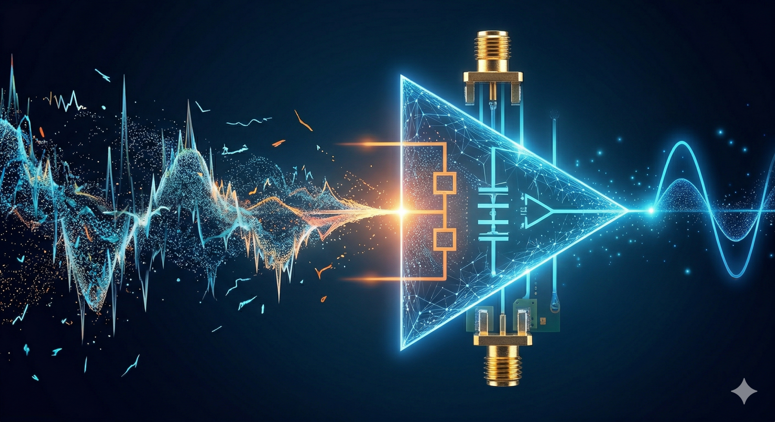
When working in RF amplifier design, one of the most important performance factors to manage is the RF amplifier noise figure. It has a direct impact on how well a system can detect weak signals, especially in applications like wireless communication, radar, and industrial IoT.
A lower noise figure leads to a better signal-to-noise ratio (SNR) and improved receiver sensitivity. In practical terms, this means more reliable signal detection and better system performance. The challenge for engineers is finding ways to reduce noise without negatively affecting gain, stability, or overall system behavior.
What Is RF Amplifier Noise Figure and Why It Matters
The RF amplifier noise figure describes how much noise an amplifier adds compared to an ideal, noise-free device. Even small increases can make a noticeable difference when working with low-level signals.
In most systems, the first stage of the RF front-end module (FEM) plays the biggest role. Once noise is introduced at this stage, it carries through the rest of the signal chain and cannot be removed later.
This is why the first amplifier is almost always a low noise amplifier (LNA), positioned as close to the antenna as possible.
Start with the Right Low Noise Amplifier (LNA)
Selecting the right low noise amplifier (LNA) is one of the most effective ways to minimize noise figure in RF systems.
When evaluating an LNA, engineers typically look at:
- Noise figure across the operating frequency range
- Gain and how it fits into the overall system
- Stability under real operating conditions
There is always a trade-off between gain and noise figure in RF systems. Increasing gain can improve sensitivity, but it needs to be balanced carefully to avoid distortion or instability.
Material choice also plays a role. GaAs and GaN amplifiers are both widely used, depending on the application. GaAs is often preferred where low noise is the priority, while GaN is used in higher power environments.
Use Proper Impedance Matching Techniques
Impedance matching has a direct and often underestimated impact on noise performance. If the input is not properly matched, reflections can reduce efficiency and increase the overall noise figure.
In LNA design, the focus is usually on noise matching, not just power matching. This means designing the input network to achieve the lowest possible noise figure, even if it results in a slight reduction in gain.
Engineers often rely on:
- Matching networks using inductors and capacitors
- Smith chart techniques
- Simulation tools to evaluate noise circles and performance
Getting the input match right is one of the most effective ways to improve overall system performance.
Minimize Insertion Loss Before the Amplifier
One of the most practical ways to reduce the RF amplifier noise figure is to minimize any loss before the signal reaches the amplifier.
Any insertion loss between the antenna and the LNA directly increases the system noise figure. This includes components like cables, connectors, filters, and switches.
Even small losses matter. For example, a 1 dB loss before the LNA can increase the overall noise figure by nearly the same amount.
This is why insertion loss minimization is so important. Careful component selection and layout decisions can make a meaningful difference.
Understand the Impact on Signal-to-Noise Ratio (SNR)
Reducing the RF amplifier noise figure improves the signal-to-noise ratio (SNR), which is a key measure of system performance.
A better SNR means:
- Weak signals are easier to detect
- Communication links are more stable
- Data transmission is more reliable in noisy environments
In real-world applications, this often translates to improved range, fewer errors, and more consistent performance.
Consider Noise Temperature in System Design
In microwave engineering, noise is often expressed as noise temperature. This provides another way to evaluate how much noise a component adds to a system.
Lower noise temperature indicates better performance and is especially useful when comparing components in high-frequency or precision applications.
Using this approach can help engineers make more informed decisions when selecting amplifiers and designing systems.
Balance Gain and Noise Figure in RF Systems
There is always a balance between gain and noise figure. While higher gain can improve sensitivity, too much gain can introduce instability or amplify unwanted signals further down the chain.
A practical approach is to:
- Use a high-performance LNA at the front end
- Maintain controlled, consistent gain throughout the system
- Avoid unnecessary amplification stages
This balance is particularly important in more complex RF front-end module (FEM) designs.
Choosing the Right Components for Long-Term Performance
In many RF systems, especially in industrial and long-life applications, component availability is just as important as performance.
Engineers often need to deal with:
- End-of-life (EOL) components
- Long lead times
- The risk of counterfeit parts
Working with a reliable supplier can help reduce these risks and ensure consistent performance over time. Access to hard-to-find and obsolete RF components is especially important when maintaining or upgrading existing systems.
Conclusion
Reducing the RF amplifier noise figure is a key part of effective RF amplifier design. By focusing on LNA selection, impedance matching, and minimizing insertion loss, engineers can improve both sensitivity and overall system reliability.
Even small improvements can lead to better signal-to-noise ratio, stronger performance in low-signal environments, and more consistent operation over time.
Taking a practical, system-level approach — along with sourcing reliable components — helps ensure designs perform as expected in real-world conditions.