
RF filters help control which frequencies pass through a radio frequency system and which are attenuated. They play an important role in wireless communications, radar, satellite systems, test equipment, and other applications where signals must be separated from unwanted interference. Choosing the right filter affects more than frequency selection. It can influence insertion loss, receiver sensitivity, transmit power handling, signal integrity, and the overall performance of an RF signal chain.
Different applications call for different filter technologies. Surface acoustic wave (SAW) and bulk acoustic wave (BAW) filters are widely used in compact communications equipment, while cavity filters are often selected for applications requiring high selectivity and power handling. LC filters, built from inductors and capacitors, offer flexibility across a broad range of circuit designs.
Understanding these differences helps engineers make informed decisions during component selection and system design. For buyers sourcing RF components, it also provides a clearer basis for comparing specifications, checking compatibility, and identifying suitable replacements when preferred parts are difficult to obtain.
What Are RF Filters and How Do They Work?
An RF filter is a frequency-selective circuit or component designed to pass a desired range of frequencies while reducing signals outside that range. Its behavior depends on the filter topology, component characteristics, operating frequency, and intended application.
In a receiver, a filter may suppress out-of-band signals before they reach a low-noise amplifier or mixer. This helps reduce the risk of strong unwanted signals interfering with weaker signals of interest. In a transmitter, filtering can limit unwanted spectral energy and help meet system emission requirements. Filters can also separate frequency bands, support duplexing arrangements, and reduce interference between sections of a larger RF system.
The main filter responses include:
Low-pass filters: Pass frequencies below a defined cutoff and attenuate higher frequencies.
High-pass filters: Pass frequencies above a defined cutoff and attenuate lower frequencies.
Band-pass filters: Pass a selected frequency band while reducing signals above and below it.
Band-stop filters: Attenuate a selected band while allowing frequencies outside that band to pass.
The response required depends on the signal environment. A receiver operating near powerful transmitters may need strong out-of-band rejection, while a compact wireless device may prioritize low insertion loss, small size, and consistent performance across manufacturing tolerances.
A filter’s performance should therefore be assessed in the context of the complete RF signal chain, rather than as an isolated specification.
Comparing the Main RF Filter Types
Four commonly encountered RF filter technologies are SAW, BAW, cavity, and LC. Each uses a different physical or electrical mechanism to achieve frequency selectivity, creating trade-offs in size, frequency range, loss, selectivity, power handling, and implementation.
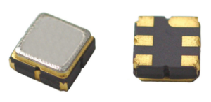
SAW filters use acoustic waves that travel along the surface of a piezoelectric substrate. Electrical input signals are converted into acoustic waves and then back into electrical signals, with the device’s structure determining its frequency response.
Their small size and suitability for mass production make SAW filters common in wireless communication equipment, including mobile devices, GPS receivers, and other radio systems operating in appropriate frequency bands.
SAW filters can provide useful selectivity in a compact package. However, their performance depends on the specific device design and operating conditions. Insertion loss, temperature sensitivity, frequency range, and power handling all need to be checked against the application.
For engineers designing compact receivers, SAW technology can be a good option when a suitable combination of bandwidth, rejection, and package size is available.
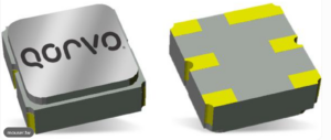
BAW filters use acoustic resonances through the thickness of a piezoelectric layer rather than waves travelling along a substrate’s surface. This construction can support high-frequency operation and strong selectivity in compact devices.
BAW technology is used in wireless systems where adjacent frequency bands need to be separated carefully. Depending on the implementation, BAW filters can offer useful performance at frequencies where a particular SAW design may face limitations.
Not all BAW filters have the same characteristics. The achievable bandwidth, insertion loss, temperature stability, and power handling depend on the architecture and specifications of the individual component. Engineers should compare measured performance across the intended operating band rather than selecting a filter based on technology name alone.
BAW filters are particularly worth evaluating in compact RF front ends where frequency separation, size, and integration requirements place tight constraints on component selection.
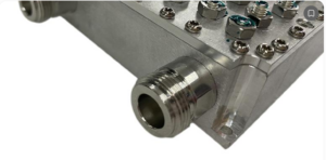
Cavity filters use resonant electromagnetic structures, often enclosed in metal cavities. Their physical dimensions and resonant characteristics determine the frequencies they pass or reject. Multiple resonators can be combined to achieve a specific bandwidth and rejection profile.
Cavity filters are commonly considered for base stations, microwave links, radar, satellite communications, and other RF systems that need strong selectivity. Depending on their design, they can handle higher power levels than many miniature acoustic filters and provide low insertion loss over suitable operating bands.
Their main trade-offs are physical size, weight, cost, and mechanical complexity. Performance can also depend on tuning, connector quality, thermal conditions, and the stability of the resonant structure.
For equipment where selectivity and power handling take priority over minimum size, cavity filters can be a suitable choice. Engineers should also account for installation space, mounting, environmental conditions, and any tuning requirements.
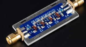
LC filters use inductors and capacitors arranged in a circuit to create the desired frequency response. They can be implemented using discrete components or integrated into a larger circuit, making them a flexible option for many RF designs.
Depending on the topology and component values, LC networks can implement low-pass, high-pass, band-pass, and band-stop responses. They are used in matching networks, signal conditioning, harmonic suppression, and other filtering applications.
Their advantages include design flexibility, availability of different component values, and integration into printed circuit boards. Their limitations can include component tolerances, parasitic capacitance and inductance, finite component quality factors, and layout sensitivity. At higher frequencies, these parasitic effects can become a major part of the filter’s behavior.
LC filters can be attractive when a circuit needs a particular response without a dedicated acoustic or cavity component. However, engineers must evaluate the complete network, including PCB layout, component tolerances, and impedance conditions, to confirm that the finished circuit meets its intended specifications.
SAW vs. BAW vs. Cavity vs. LC: Comparison Table
The table below summarizes typical characteristics of each technology. These are general design tendencies, not guaranteed specifications. Performance varies with frequency, topology, materials, component quality, and the requirements of the particular application.
Characteristic | SAW filters | BAW filters | Cavity filters | LC filters |
|---|---|---|---|---|
Operating frequency | Commonly used from lower RF bands into GHz ranges, depending on design | Commonly used in GHz-range wireless applications, depending on design | Used from RF into microwave bands, depending on cavity design | Used across broad frequency ranges, with practical limits set by components and layout |
Selectivity | Good for many compact band-selection applications | Can provide strong selectivity in compact RF front ends | Often excellent; multiple resonators can provide high rejection | Varies with topology, component quality, and filter order |
Insertion loss | Device-dependent; must be checked across the passband | Device-dependent; design and bandwidth affect loss | Can be low in well-designed resonant structures | Depends on inductor and capacitor quality, topology, and frequency |
Physical size | Generally very small | Generally very small | Usually larger than chip-level filters | Can be compact, although size depends on frequency and component values |
Power handling | Often limited compared with larger resonant structures | Depends on device design; check specified power limits | Often suitable for higher-power applications when designed accordingly | Depends on component ratings, current, voltage, and thermal limits |
Integration | Well suited to compact packaged RF modules | Well suited to compact RF front ends | Typically requires more board or chassis space | Can be built directly into a PCB circuit |
Main strengths | Small size and useful frequency selectivity | Compact size and selectivity for suitable high-frequency applications | Selectivity and potential for low loss and higher power handling | Flexibility, configurable response, and circuit-level integration |
Main trade-offs | Frequency and temperature behavior, loss, and power limits | Device-specific loss, bandwidth, and power constraints | Size, weight, cost, and possible tuning requirements | Tolerance sensitivity, parasitics, layout effects, and finite component Q |
Typical applications | Wireless devices, compact receivers, selected GPS and communications systems | Cellular and other compact wireless RF front ends | Base stations, radar, microwave links, and selected satellite systems | Matching networks, RF signal conditioning, harmonic filtering, and general circuit design |
How should engineers use this comparison?
Start with the operating frequency, required bandwidth, and rejection of unwanted signals. These requirements help narrow the technology choices. Next, evaluate insertion loss, impedance, power handling, environmental conditions, and available space.
A small receiver may favor a SAW or BAW filter if the required frequency response is available. A high-power RF path may call for a suitable cavity filter. An LC network may be a better fit when the response needs to be incorporated into a custom circuit or matching network.
These are starting points, not fixed rules. The final decision should be based on the component datasheet and, where necessary, measured performance in the intended circuit.
Key Specifications to Check When Selecting RF Filters
Technology type is only one part of filter selection. Two filters using the same technology can perform differently, so engineers should compare the specifications that affect the intended signal path.
Insertion loss and return loss
Insertion loss measures the reduction in signal power as the desired signal passes through the filter. Excessive loss in a receiver’s front end can reduce the signal level reaching later stages and affect overall receiver sensitivity.
Return loss describes how well the input or output is matched to the reference impedance. Poor matching can cause reflections, affecting power transfer and system performance. For most RF systems, both specifications should be assessed across the complete passband, not just at a single frequency.
Bandwidth and rejection
Bandwidth defines the range of frequencies the filter is designed to pass. A filter with insufficient bandwidth may attenuate wanted signals, while excessive bandwidth can allow unwanted signals into the next stage.
Rejection, often expressed in decibels, indicates how strongly a filter attenuates signals outside the passband or within specified stopbands. Engineers should pay particular attention to nearby interferers, harmonics, and other signals that could overload sensitive components or disrupt system operation.
Power handling and linearity
In transmit paths, a filter must withstand the expected average and peak power levels. Exceeding its ratings can lead to excessive heating, degraded performance, or component damage. In high-power systems, engineers should check thermal limits and the manufacturer’s specified power conditions.
Linearity can also matter when a filter operates in the presence of multiple strong signals. Depending on the technology and application, nonlinear behavior may contribute to unwanted signal products. The relevant specifications should be considered alongside the requirements of the complete transmitter or receiver.
Temperature stability and tolerances
Filter performance can change with temperature, manufacturing variation, aging, and mechanical conditions. These effects matter in equipment exposed to outdoor environments, temperature cycling, or tight frequency tolerances.
Engineers should check the specified operating temperature range, frequency stability, and applicable environmental ratings. For designs requiring consistent performance across many units, manufacturing tolerances and production testing may also influence the choice.
Matching Filter Technology to the Application
The most suitable filter depends on the system’s priorities and operating environment.
In wireless communications, adjacent-channel rejection and compact packaging may be key requirements. In radar and electronic warfare systems, engineers may need to balance selectivity, instantaneous bandwidth, power handling, and the ability to operate in demanding signal environments. Satellite and microwave communications can place particular emphasis on insertion loss, frequency stability, and performance across the intended operating band.
Test and measurement equipment introduces other considerations. Filters may need to support a defined measurement bandwidth, reduce unwanted signals, or maintain predictable performance across a specified frequency range. In each case, the correct technology is the one that meets the system’s requirements within its size, power, cost, and integration constraints.
It is also important to consider the filter’s position in the RF signal chain. A filter placed before a low-noise amplifier has different implications for receiver sensitivity than one positioned after a gain stage. Likewise, a filter in a transmit path must be evaluated for its effect on power delivery and spectral performance.
This system-level approach helps avoid choosing a component based on a single attractive specification while overlooking a limitation elsewhere in the design.
RF Filter Sourcing: What Engineers and Buyers Should Consider
Selecting a technically suitable filter is only part of the procurement process. The exact part number, package, frequency response, electrical ratings, and production status all matter when sourcing components for new designs or existing equipment.
For engineers maintaining established systems, a preferred filter may become difficult to obtain because of extended lead times, product discontinuation, or changing supplier availability. Replacing it with a component that appears similar on paper can introduce differences in insertion loss, bandwidth, rejection, impedance, or physical fit.
When evaluating an alternative, compare the full datasheets and confirm the operating conditions behind the published specifications. Where a direct replacement is unavailable, determine which parameters are mandatory and which can accommodate a change. Testing the proposed component in the intended circuit may be necessary before approving it for production.
Supply-chain assurance is another consideration. RF filters used in communications, radar, aerospace, and other demanding systems should be sourced through appropriate channels, with attention to traceability, authenticity, and documentation. These measures help reduce the risks associated with questionable or incorrectly represented components.
Rfiber Solutions supports customers sourcing RF, microwave, and related electronic components, including parts that may be difficult to locate through standard distribution channels. For engineering and procurement teams, a clear part number, the required specifications, quantity, and delivery timeline provide a useful starting point when investigating component availability.
Conclusion: Choosing the Right RF Filters
RF filters are an important part of effective RF system design, but no single technology is the best choice for every application. SAW and BAW filters can meet the needs of compact wireless systems, cavity filters can suit applications requiring strong selectivity and higher power handling, and LC filters offer flexibility for circuit-level filtering and signal conditioning. By comparing frequency response, insertion loss, rejection, power handling, temperature stability, and integration requirements, engineers can make better-informed decisions. When a suitable component is difficult to source or an existing part is approaching end of life, Rfiber Solutions can help businesses investigate RF and microwave component availability to support their design, maintenance, and procurement requirements.